Maximum Hydraulic Component Life
- Home >
- articles >
- mechanical >
- hydraulic component
Defining Fluid Temperature & Viscosity Limits for Maximum Hydraulic Component Life
By Brendan Casey
Many factors can reduce the service life of hydraulic components. Incorrect fluid viscosity is one of these factors. To prevent low (or high) viscosity from cutting short component life, an appropriate fluid operating temperature and viscosity range must first be defined and then maintained on a continuous basis. Before I discuss this in detail, let me explain the interrelationship of fluid temperature and viscosity, and how they impact upon hydraulic component life.
Temperature/Viscosity Relationship of Hydraulic Fluid
The viscosity of petroleum-based hydraulic fluid decreases as its temperature increases and conversely, viscosity increases as temperature decreases. This is why limits for fluid viscosity and fluid temperature must be considered simultaneously. Low fluid viscosity can result in component damage through inadequate lubrication caused by excessive thinning of the oil film, while excessively high fluid viscosity can result in damage to system components through cavitation.
Manufacturers of hydraulic components publish permissible and optimal viscosity values, which can vary according to the type and construction of the component. As a general rule, operating viscosity should be maintained in the range of 100 to 16 centistokes (460 to 80 SUS), however viscosities as high as 1000 centistokes (4600 SUS) are permissible for short periods at start up. Optimum operating efficiency is achieved with fluid viscosity in the range of 36 to 16 centistokes (170 to 80 SUS) and maximum bearing life is achieved with a minimum viscosity of 25 centistokes (120 SUS).
Hydraulic Fluid Viscosity Grades
ISO viscosity grade (VG) numbers simplify the process of selecting a fluid with the correct viscosity for a system's operating temperature range. A fluid's VG number represents its average viscosity in centistokes (cSt) at 40°C. For example, an ISO VG 32 fluid has an average viscosity of 32 centistokes at 40°C. Note that the average fluid viscosity of ASTM and BSI viscosity grade numbers are measured at 100°F (38.7°C). This means that fluids of a given ASTM or BSI grade are slightly more viscous than the corresponding ISO grade.
Determining the Correct Viscosity Grade
In order to determine the correct fluid viscosity grade for a particular application, it is necessary to consider: " starting viscosity at minimum ambient temperature; " maximum expected operating temperature, which is influenced by maximum ambient temperature; and " permissible and optimum viscosity range for the system's components.
In most cases, the machine manufacturer will specify the correct viscosity grade. It is important to understand that the machine manufacturer's recommended viscosity grade should change as the ambient temperature conditions in which the machine operates change.
I say this because several years ago I was involved in the analysis of several premature component failures from a mobile hydraulic machine. The machine was designed and built in the Northern Hemisphere, but was operating in high ambient air temperatures in the Southern Hemisphere. The components had failed due to inadequate lubrication, because of low fluid viscosity.
Investigation revealed that the fluid in the system was ISO VG 32. While this viscosity grade is suitable for cooler climates found in parts of the Northern Hemisphere, it was not suitable for the high ambient temperatures in which this machine was operating. The machine owner confirmed that the manufacturer's fluid recommendation was indeed ISO VG 32.
The machine manufacturer had not altered their fluid viscosity recommendation to take into account the higher ambient temperatures in which this particular machine was operating. This oversight resulted in several premature component failures because of low fluid viscosity.
The machine manufacturer's viscosity grade recommendation can be checked using the viscosity/temperature diagram shown in exhibit 1, assuming the minimum starting temperature and the hydraulic system's maximum operating temperature are known. For example, let's consider an application where the minimum ambient temperature is 15°C, the system's maximum operating temperature is 75°C, the optimum viscosity range for the system's components is between 36 and 16 centistokes and the permissible, intermittent viscosity range is between 1000 and 10 centistokes.
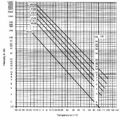
From the viscosity/temperature diagram in exhibit 1 it can be seen that to maintain viscosity above the minimum, optimum value of 16 centistokes at 75°C, an ISO VG 68 fluid is required. At a starting temperature of 15°C, the viscosity of VG 68 fluid is 300 centistokes, which is within the maximum permissible limit of 1000 centistokes at start up. If the machine manufacturer's recommendation was ISO VG 32 fluid under the same conditions, I would question it.
A word of warning here - do not change the fluid viscosity grade in a system without consulting the equipment manufacturer. Doing so may void the manufacturer's warranty and/or cause damage to the system's components.
Defining Operating Temperature Limits
Having established that the fluid in the system is the correct viscosity grade for the ambient temperature conditions in which the machine is operating, the next step is to define the fluid temperature equivalents of the optimum and permissible viscosity values for the system's components.
By referring back to the viscosity/temperature curve for VG 68 fluid in exhibit 1, it can be seen that an optimum viscosity range of between 36 and 16 centistokes will be achieved with a fluid temperature range of between 55°C and 78°C. The minimum viscosity for optimum bearing life of 25 centistokes will be achieved at a temperature of 65°C. The permissible, intermittent viscosity limits of 1000 and 10 centistokes equate to fluid temperatures of 2°C and 90°C, respectively.
Going back to our example, this means that with an ISO VG 68 fluid in the system, the optimum operating temperature is 65°C and maximum operating efficiency will be achieved by maintaining fluid temperature in the range of 55°C to 78°C. If cold start conditions at or below 2°C are expected, it will be necessary to pre-heat the fluid to avoid damage to system components. Intermittent fluid temperature in the hottest part of the system, which is usually the pump case, must not exceed 90°C.
Note that fluid temperatures above 82°C (180°F) damage seals, reduce the service life of the hydraulic fluid and in most cases, will cause the viscosity limits of the fluid to be exceeded. This means that the operation of any hydraulic system at temperatures above 82°C (180°F) is detrimental and should be avoided.
Preventing Damage Caused by High Temperature Operation
To prevent damage caused by high fluid temperature and/or low fluid viscosity, a fluid temperature alarm should be installed in the system and all high temperature indications investigated and rectified immediately. The over-temperature alarm should be set to the temperature at which the minimum, optimum viscosity value is exceeded. As already explained, this will be dependent on the viscosity grade of the fluid in the system. In the example discussed above, the fluid temperature alarm would be set at 78°C.
Continuing to operate a hydraulic system when the fluid is over-temperature is similar to operating an internal combustion engine with high coolant temperature. Damage is almost guaranteed. Therefore, whenever a hydraulic system starts to overheat, shut down the system, find the cause of the problem and fix it!
About the Author: Brendan Casey has more than 15 years experience in the maintenance, repair and overhaul of mobile and industrial hydraulic equipment.